-40%
Arduino XBee and Prototyping Shield
$ 5.78
- Description
- Size Guide
Description
Arduino XBee and Prototyping ShieldWRL-12847
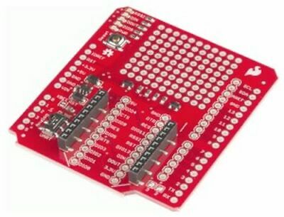
Arduino XBee Module and Prototyping Shield (Add-on Board)
The XBee Shield simplifies the task of interfacing an
XBee Module
with your Arduino microcontroller board. The shield form factor mates directly with any development board that has an Arduino R3 standard footprint and equips it with wireless communication capabilities using popular XBee modules. This unit works with all XBee modules including the Series 1 and 2, standard and Pro versions.
The serial pins (DIN and DOUT) of the XBee are connected through an SPDT switch, which allows you to select a connection to either the UART pins (D0, D1) or any digital pins on the Arduino (D2 and D3 default). Power is taken from the 5V pin of the Arduino and regulated on-board to
3.3V DC
before being supplied to the XBee. The shield also takes care of level shifting on the DIN and DOUT pins of the XBee. For this version of the XBee Shield, the diode level shifter has been replaced with a more robust MOSFET level shifter.
The board also includes LEDs to indicate power and activity on DIN, DOUT, RSSI, and DIO5 pins of the XBee. The Arduino's reset button is brought out on the shield, and a 9×11 grid of 0.1" holes are available for prototyping. The shield does
not
come with installed headers or an XBee.
The recommended headers are the
Arduino Stackable Female Header Kit for R3
.
Arduino XBee Shield Features
Mounts directly onto your Arduino
DIN and DOUT pins of XBee can be connected either to the UART pins or to any digital pin on the Arduino (D2 and D3 by default)
3.3V power regulation and MOSFET level shifting on board
9×11 grid of 0.1"-spaced prototyping holes
Reset button brought out to shield
Power, DIN, DOUT, RSSI and DIO5 indicator LEDs
LED Indicators
There are five LEDs on the XBee Shield. Each of these LEDs connects to a pin on the XBee, which does most of the LED driving. Here's a table explaining the operation of each LED:
Label
Color
XBee Pin
Default Operation Notes
RSSI
Green
PWM0/RSSI
Indicates relative signal strength (RSSI) of last received transmission.
DIN
Green
DIN
Indicates wireless data are being transmitted.
DOUT
Red
DOUT
Indicates wireless data are being received.
DIO5
Green
Associate/DIO5
Associated indicator — blinks when the XBee is associated with another XBee.
PWR
Red
3.3V
Indicates power is present.
These LEDs can be very useful for debugging. The DIO5/Associate indicator should blink when the XBee is paired with a compatible device. The RSSI LED is actually PWM'd so it will be brighter when the paired XBee is closer


